Over the last couple of posts, I’ve been building up to completion of a DCC system assembled from MERG kits.
Last week, I had the pleasure of taking it to the South London Group’s clubroom, to trial it with our new layout. It worked!
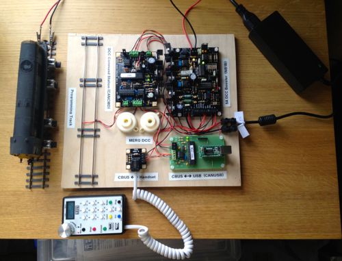
What we can see here is (starting at the loco on rollers), a class 20 on the ‘layout’ output of the system. To the right is the programming track, and alongside that we can see the command station. This provides the DCC signal for the layout, and a direct connection to the programming track. The command station has no directly attached controls, and cabs (one is at the bottom) are connected over CBUS. Since CBUS is a publicly documented standard, I intend to develop custom handsets over time. I’m intrigued if exhibition layouts will be easier to use if the controls are designed with the operation of the particular layout in mind.
To the right of the picture, the top board is a 5A DCC booster, which provides the actual layout power and DCC signal broadcast. Below it is a USB to CBUS connection. Not directly needed for the system to function, it will facilitate future firmware upgrades to the command station and handset, and permit me to prototype the custom handsets on a PC before committing them to electronics.